Structures
For future use in VR, it was decided to model the building in which Neomatt is housed. Though not really intended for parametric modelling, it’s still possible to create a geometric model with fairly accurate dimensions. The following is a simple method for creating such a model.
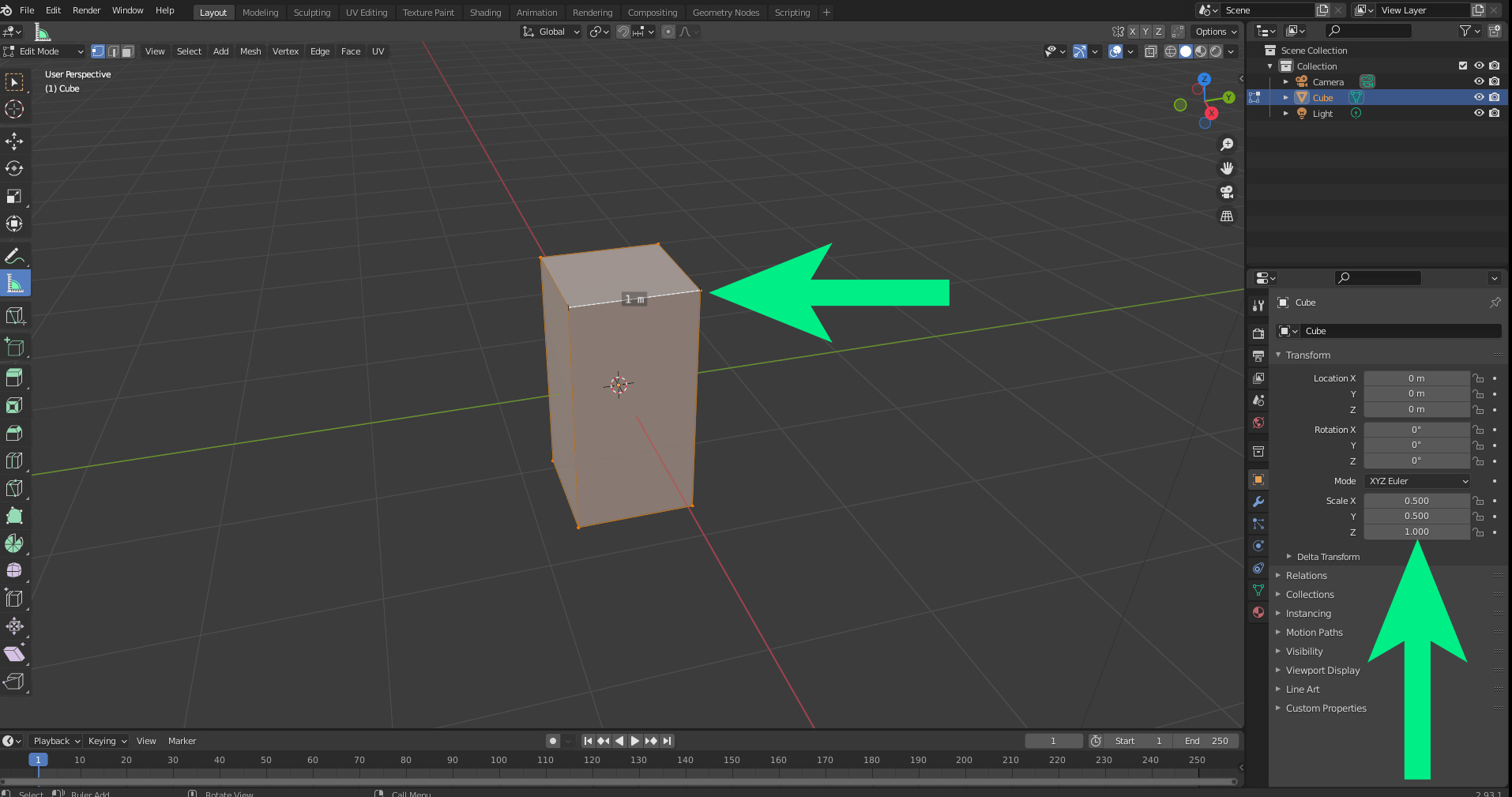
To begin with, we need to resize the cube so that it’s easier to resize to the measured sizes of the elements of the building. In edit mode, scale to 0.5 on the x and y z. The default block is 2 metres, so scaling by half will make it 1x1m on the x and y axes. You can use the on screen measuring tape to make certain and hold Ctrl to snap it to vertexes. NOTE- the image has been scaled on the x and y but not the z axis.
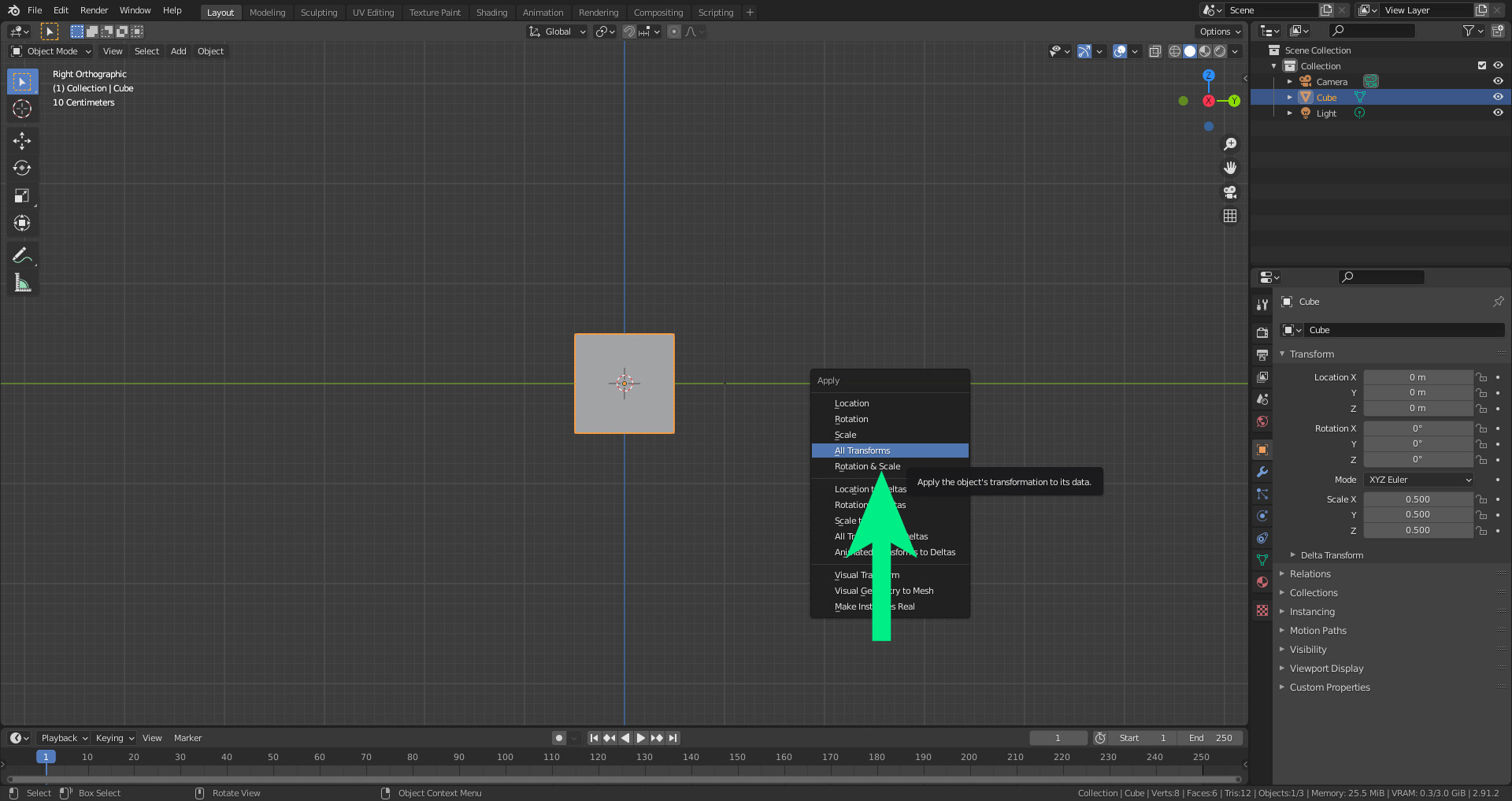
Switch back to object mode (tab) and push Ctrl + A to apply the transformation. Choose “apply all”, and the block will now have a value of 1 on the x y and z. In other words, the 1 on the x and y now equals 1 metre.
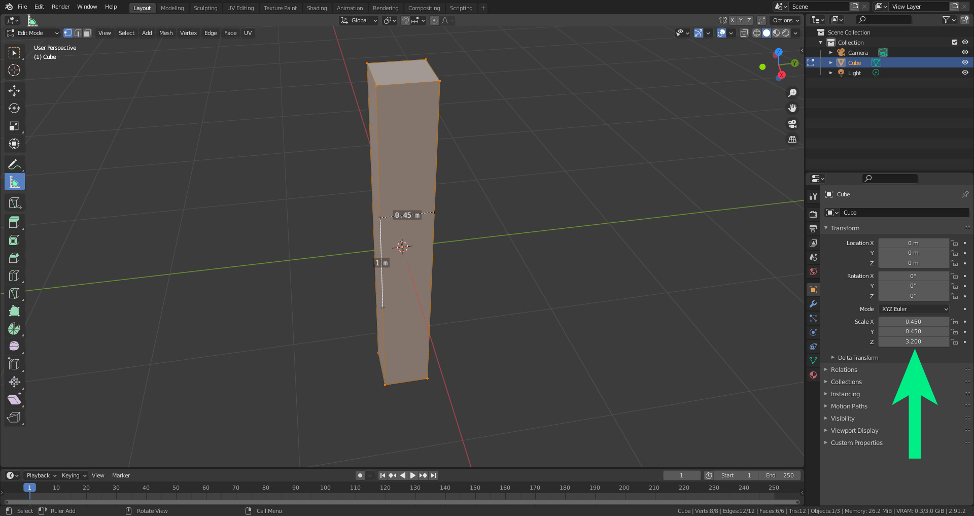
The corner of the building to the first window is 45cm. The distance from floor to ceiling is roughly 3.2 metres. Now that the block is 1x1x1m, we can scale it to these dimensions easily on all axes.
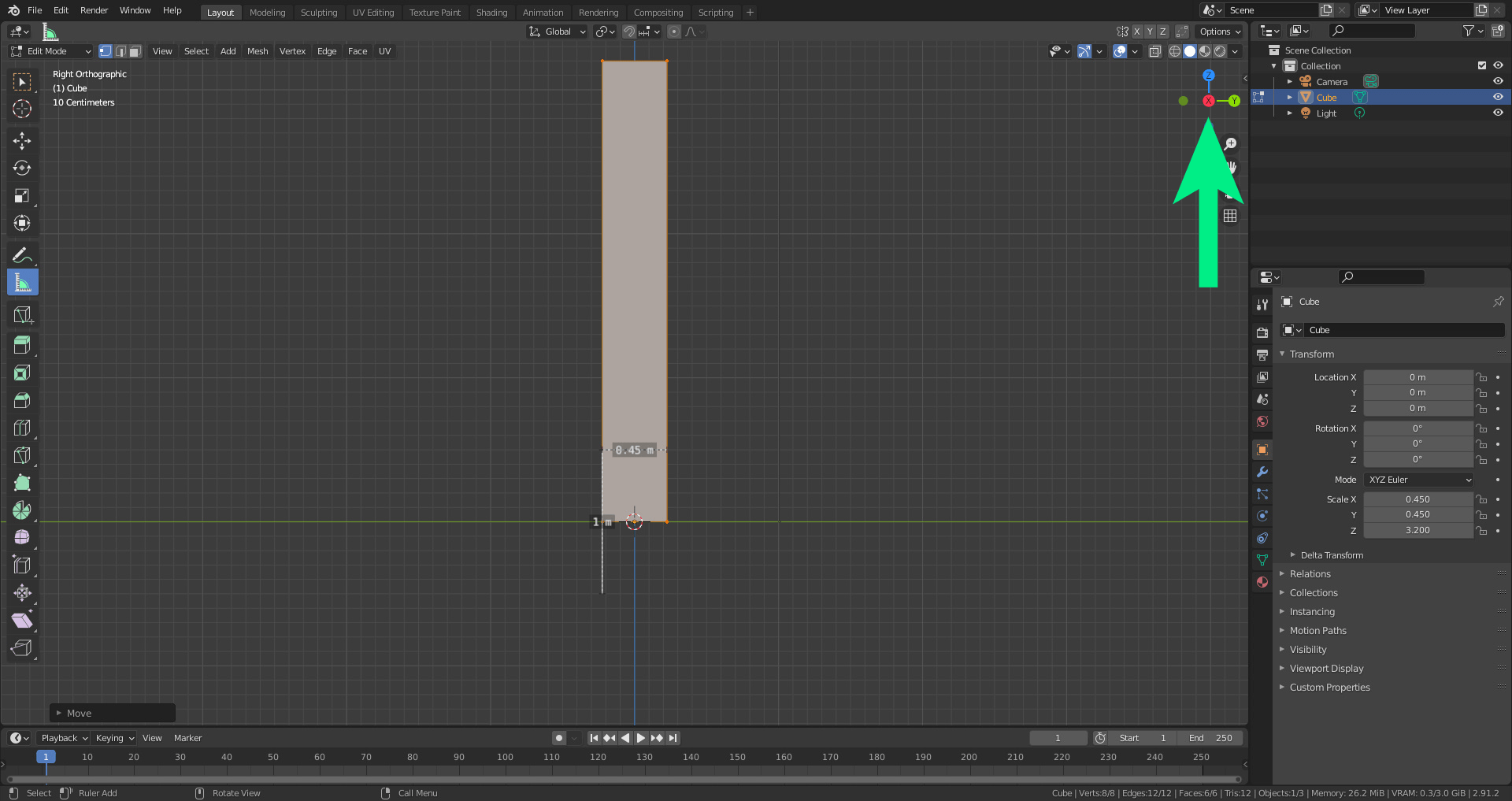
When modelling, it’s often helpful to use the isometric view. This can be done but clicking on the axis you want to view the model from. Click it again to switch sides.
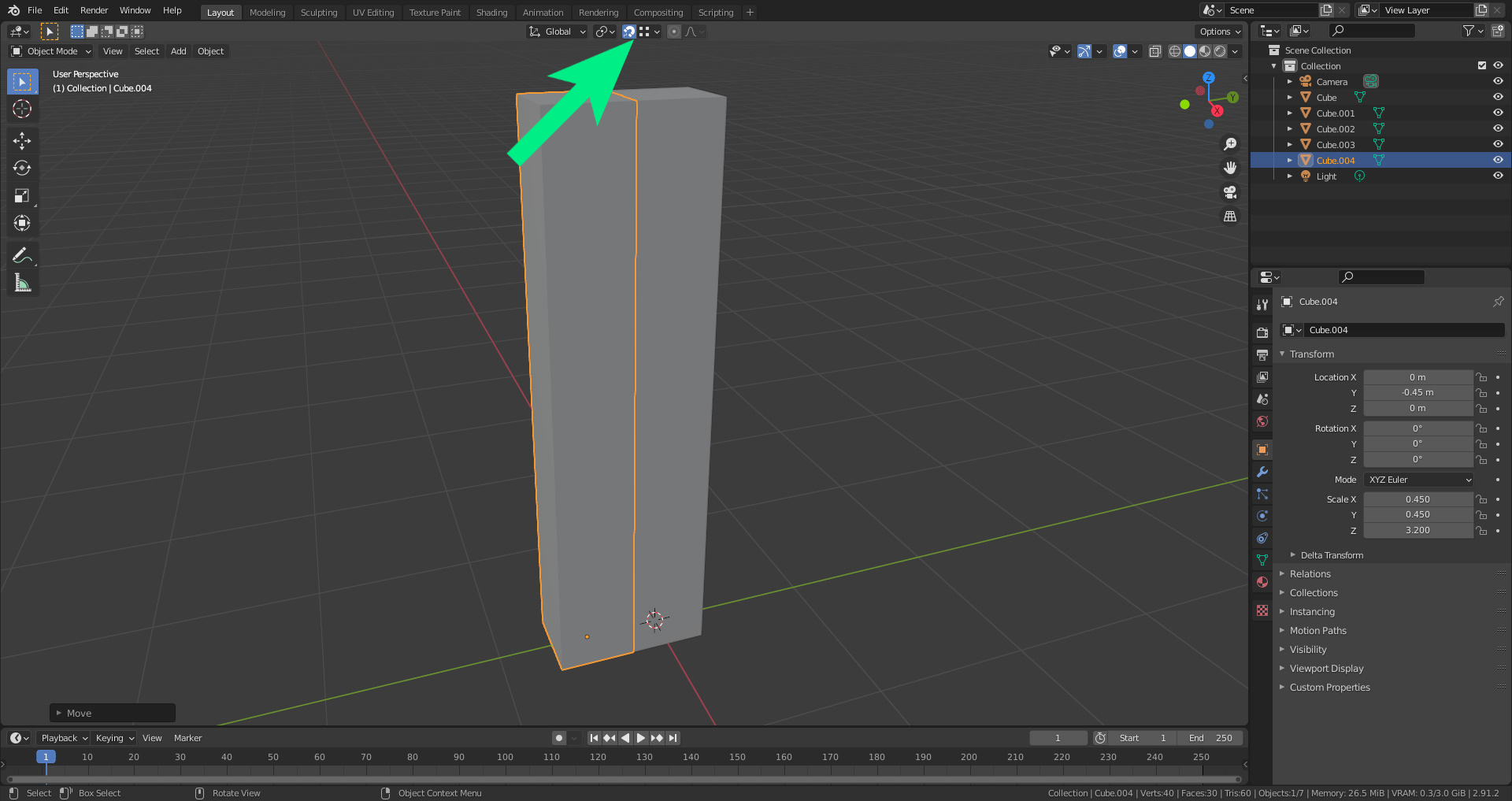
Now that we have the corner block, we can use it as a basis for the rest of our components, since it has the correct height anyways. In object mode, duplicate the block with ctrl+D, then move it with G. Snapping can be turned on to make it easier to position the blocks. With vertex snapping on (see arrow), position the block next to the first. If it doesn’t snap at first, place the block, turn the camera and try again.

We need to scale the second block for the space where the window will go. The windows are 1.11 m wide, so we need to scale up the width to reflect this. If the block interesects the first, simply use G to snap it back into place.
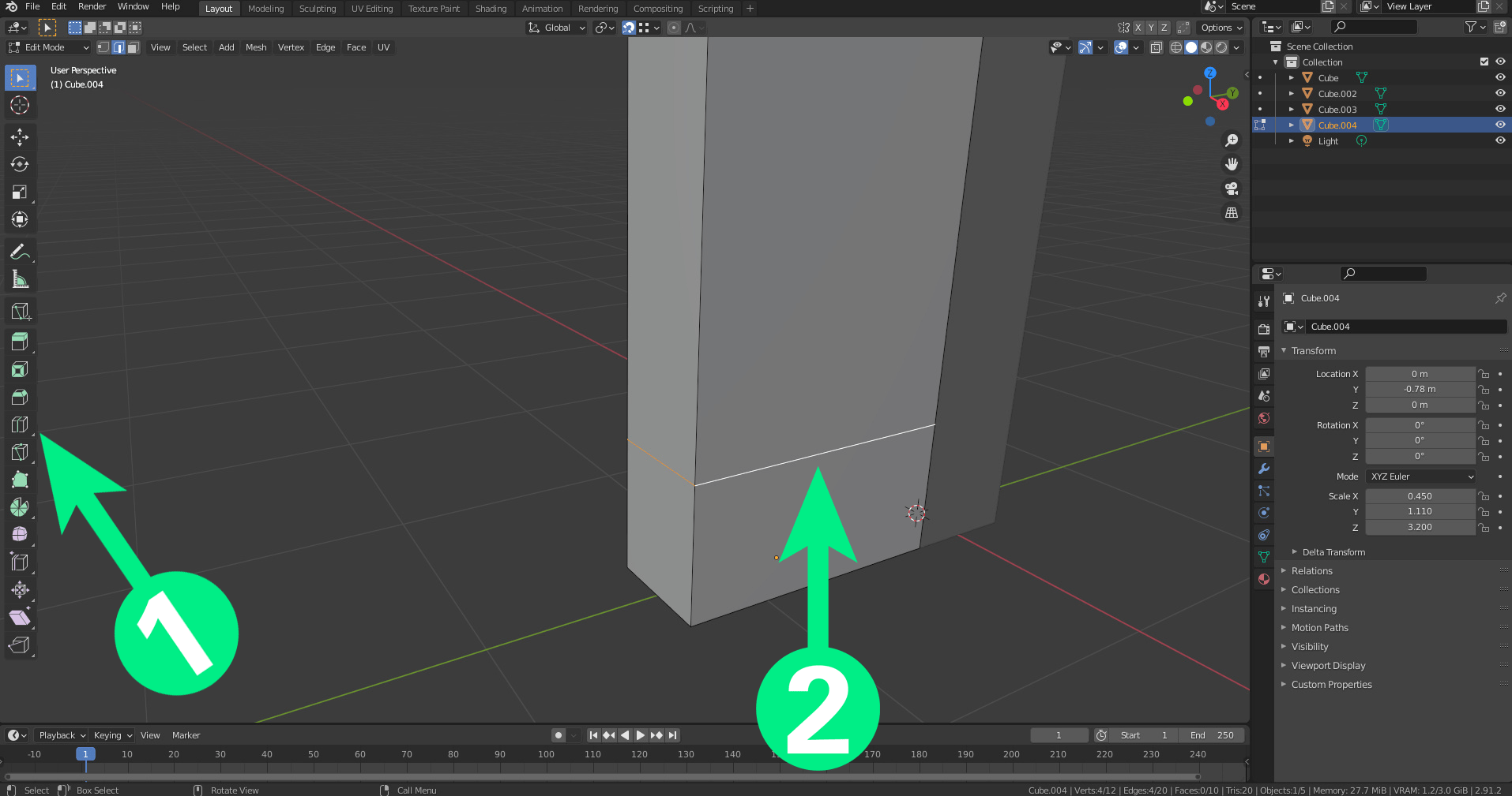
The windows are 54cm from the ground, so we have two options to create this distance. In this case, I measured with the tape measure and then used the loop cut tool (1) to create new edges and vertexes (2). Click and hold to drag the loop cut to where you’d like it. The other option is to select the bottom faces and extend 54cm, which might actually be easier.
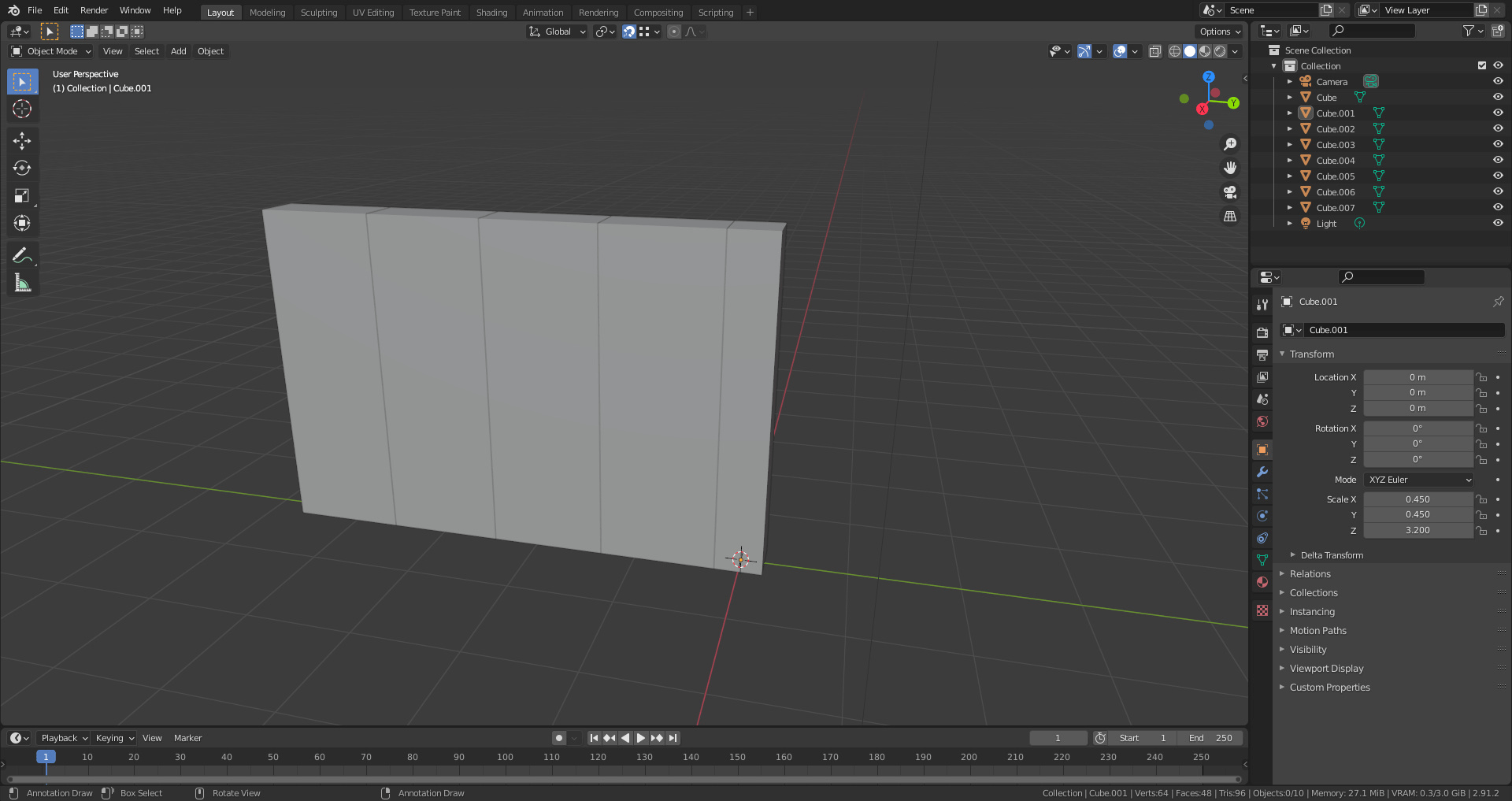
Now that the total height of the blocks is set, we can duplicate again, this time making the space between the windows 1m. Snap into place, then select both blocks and duplicate again.
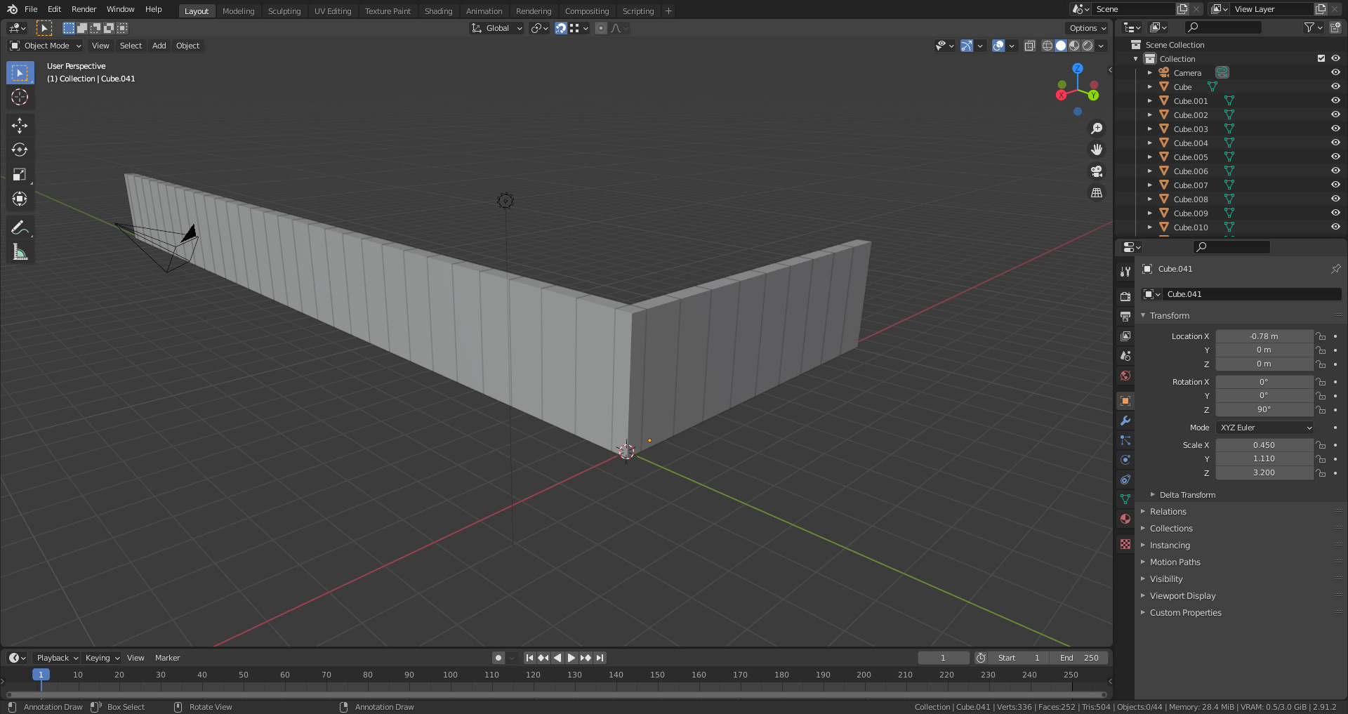
Repeat this process until the entire length and width of the building are reached. In this case it’s 29 blocks long and 9 wide.
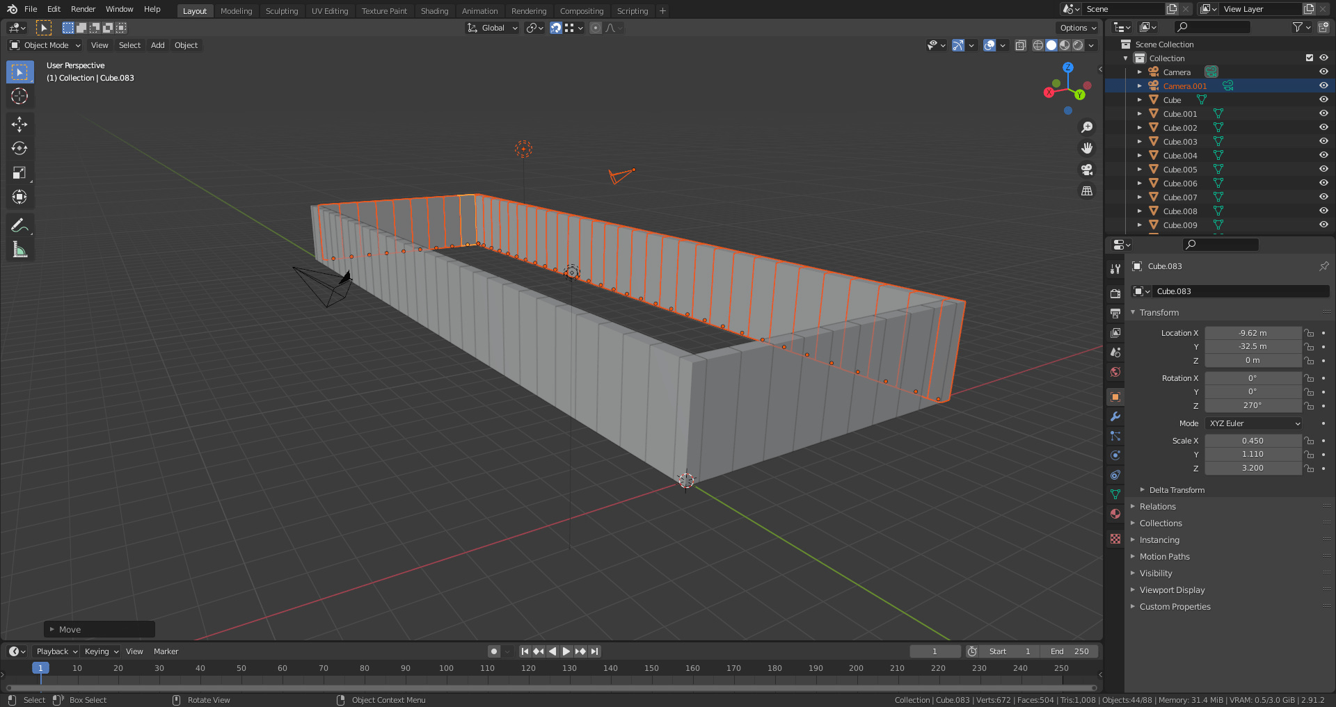
Select all the blocks (shortcut A), duplicate (Shift+D) and rotate them by pressing R, then Z to lock to this axis, then type 180 and press enter. The duplicated blocks should now create the two missing walls. Snap them into place using the method mentioned above.

Using the viewer, ensure all blocks are selected (see arrow). Then right click and choose “join” (1).
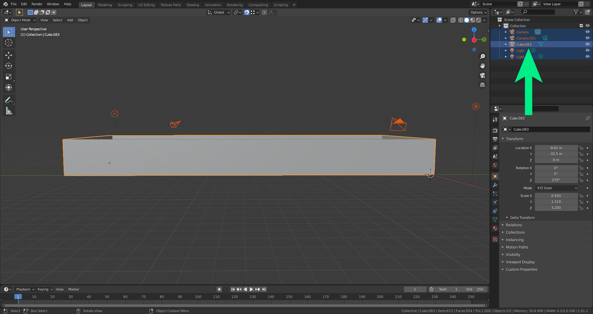
The blocks should now be combined into one single mesh.
Windows
The next step is extruding windows. There are multiple methods to do this. The first method is using the loop cut tool (outlined above) before duplicating the bricks, so that the correct height is preset. The second method is shown here.
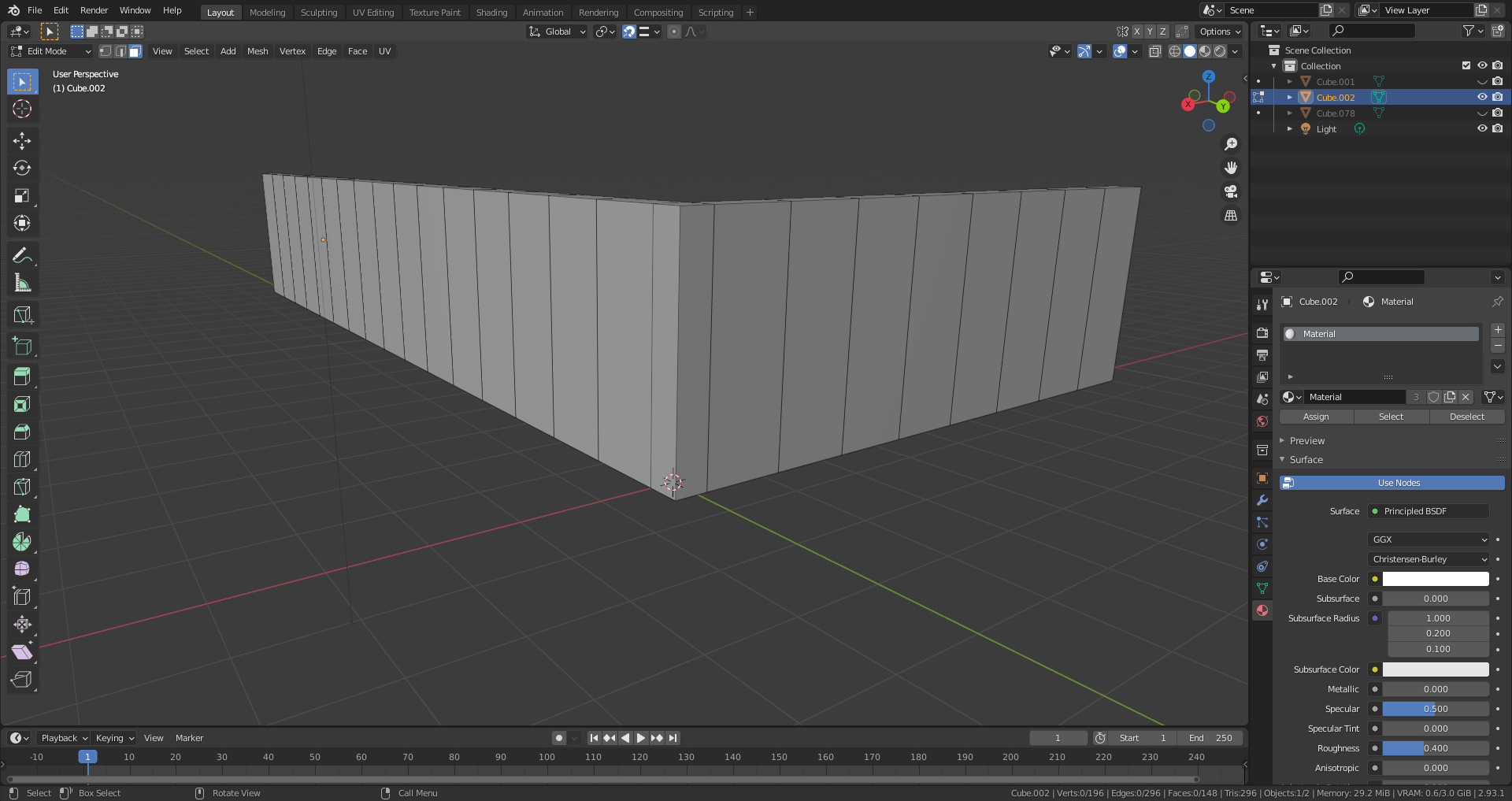
Notice that the blocks are not cut.
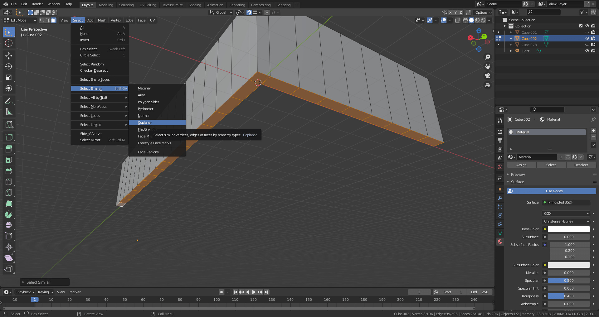
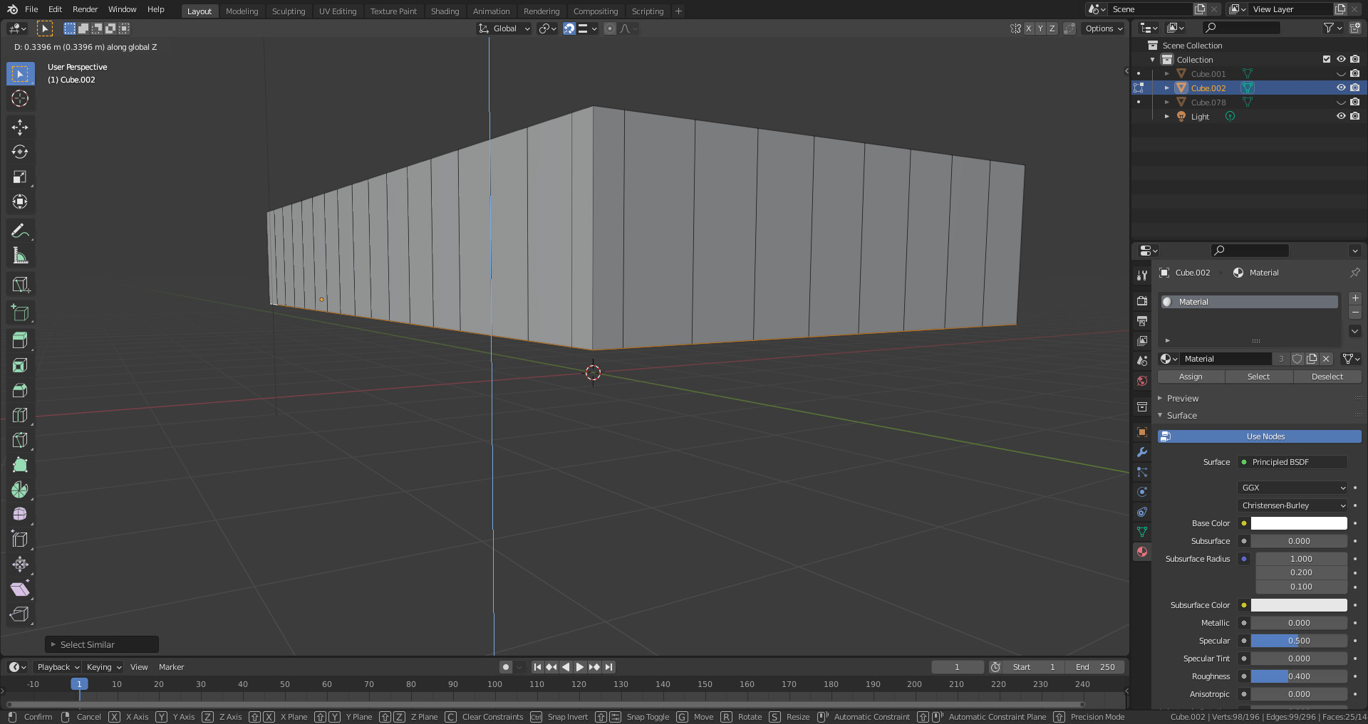
Rotate under the model and select a face. Use Select- Select Similar- Coplanar Faces. This will automatically choose all faces on the same plane. It’s also possible to choose each face individually.
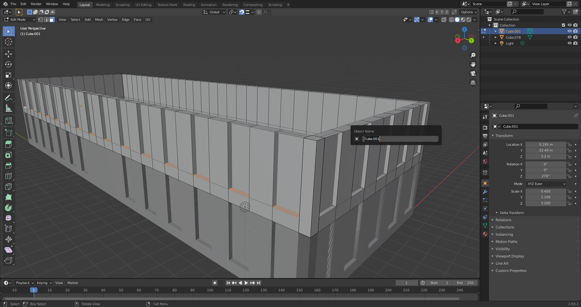
With all faces selected, choose the “move” shortcut (G), and lock the movement to the Z axis (Z). The bottom faces of all the blocks can now be moved upwards either with the mouse or with the Location options under “Object Properties” on the right side interface
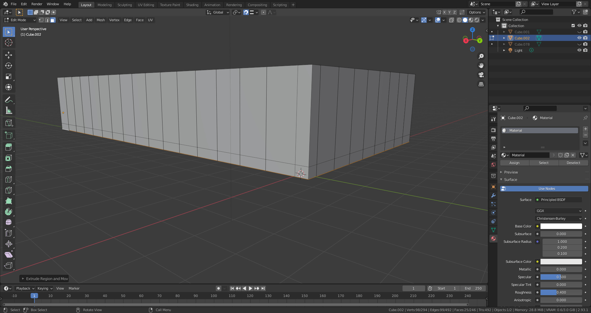
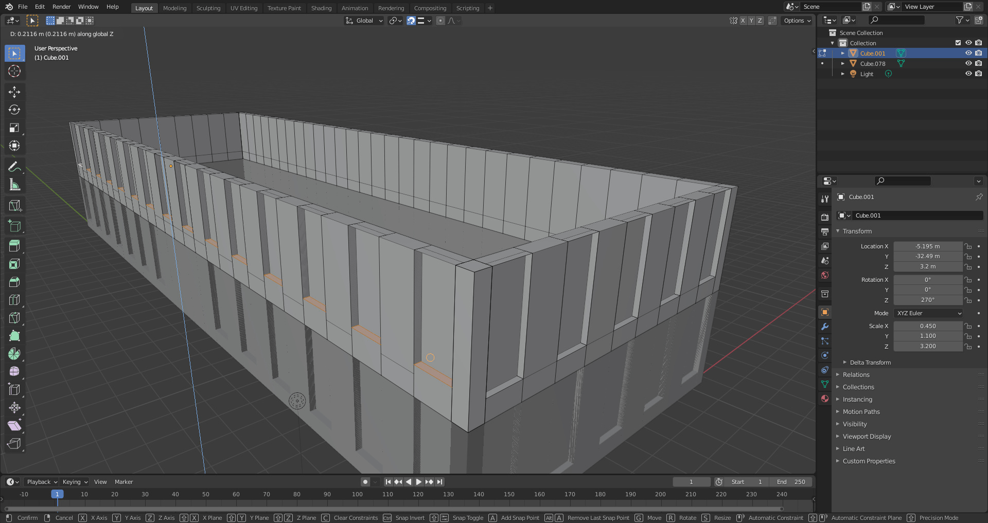
With the faces still selected, use the extrude tool (E) and lock again to the Z axis (Z). Extrude downwards back toward the ground plane using the mouse or object properties.
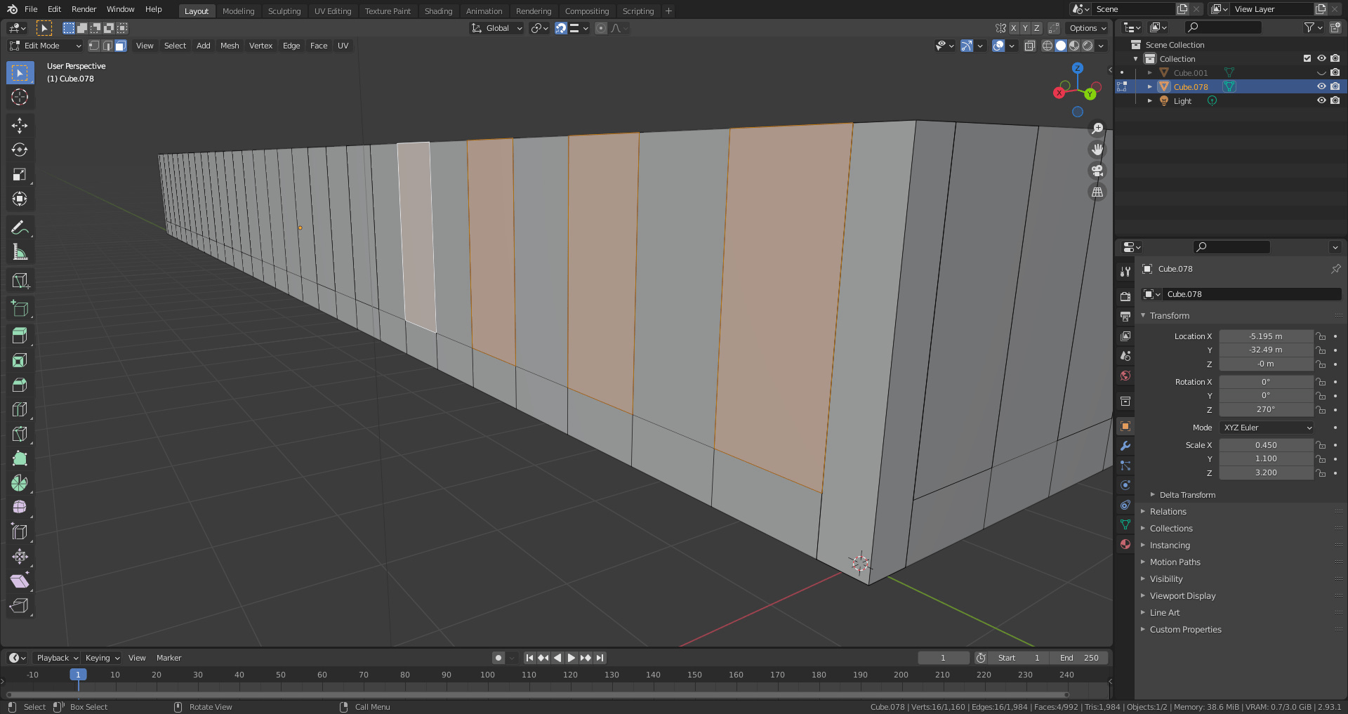
Through extruding the surfaces, there are now new divisions in the structure of the blocks. Select all faces that are to be windows and extrude (E) along the X axis (or on the Y axis as the case may be).
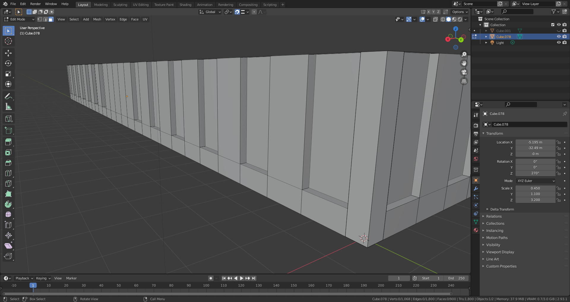
There are now insets in which the windows can be “installed”.

Select everything (A) and duplicate (shift+D), and with corner snapping turned on, move the duplicate upwards to create the first floor.
The first floor windows are not as tall as those on the ground floor, to change this select the bottom face of all the windows (select- select similar- coplanar).
Move them updwards with the move shortcut (G) and locked on the X axis. Turn off snapping (at the top) to make this easier.